Introduction
When it comes to heavy automation equipment, material handling systems, and construction equipment, unexpected failuresin worm gearbox systems have been identified as major contributors to production line downtime. Such failures can be in the form of overheating, unusual noise, excessive wear, or even failure of the self-locking feature, thus causing “runaway” conditions. According to statistics, up to 80% of unexpected worm gearbox failures can be attributed to insufficient systemic analysis of the transmission ratio, material pairing, and thermal management in the design phase rather than manufacturing defects. The problem lies in the fact that worm gearbox systems are considered standard catalog items for selection. Reliability actually comes from a systemic approach to understanding the synergistic interaction of tribology, thermodynamics, and structural mechanics. In isolation, optimization of a single parameter, like designing for an ultra-high transmission ratio for efficiency, can lead to thermal runaway. Similarly, neglecting material pairing can cause catastrophic wear.
This article is a dissection of a “Systematized Worm Gear Engineering”framework. This framework is intended to assist engineers in how to go beyond component part drawings, beginning with the design triangle of ratio, efficiency, and self-locking performance. Through scientific material selection, micro-geometric control, and assembly verification, it changes the development of a worm drive from a high-risk endeavor of empirical trial and error into a predictable and high-reliability performance engineering exercise. First of all, we shall investigate this design triangle and learn how to avoid trading away reliability for a single parameter.
The “Iron Triangle” of Worm Gear Design: How to Balance Ratio, Efficiency, and Self-Locking Without Compromise?
This section of the paper explores the fundamental compromises of worm gear design and suggests that a truly effective design strikes a dynamic balance among gear ratio, mechanical efficiency, and self-locking performance.
1. The Inherent Trade-Offs of the System
Worm gear design is subject to an unyielding “Iron Triangle.”A gear ratio is desirable for its torque multiplying capabilities but sacrifices mechanical efficiencyand heat dissipation. Pursuing a self-lock guarantee by specifying an unreasonably small lead angle for the gear teeth is counterproductive and may create manufacturing issues and binding. A truly effective design is one where all three corners of the triangle are optimized for a particular application, rather than where one is maximized at the expense of the others. This is accomplished by moving beyond static peak torque calculations and applying a more dynamic approach.
2. Engineering a Balanced Solution
The key is balancing these design considerationsthrough a systems approach. For a conveyor belt that is frequently stopped and started, there may need to be a compromise on efficiency for absolute self-locking safety. For a continuously running device such as a mixer, thermal management through increased efficiency could take precedence, potentially compromising on a guarantee of self-locking against back-driving forces. However, these decisions need to be made thoughtfully and based on data rather than default. Engineering principles and standards, for example from the American Society of Mechanical Engineers (ASME), provide the basic principles for these calculations.
3. The Cost of Imbalance
This triangle, if ignored, will lead to failures in the field. Over-ratioing the gearset will cause overheating, which will destroy the lubricant and lead to excessive wear on the gears. The inefficiency will lead to costly cooling arrangements, and an unreliable self-lock will be a safety problem. The design phase is the most cost-effective time to resolve these issues. For the reader to achieve a complete mastery over the engineering concepts and case studies involved in this balancing act, this in-depth guide to worm gear manufacturing will take the reader from theory to practice.
Beyond “Hard Steel, Soft Bronze”: How Does Material Science Dictate a 4X Service Life?
This section of the paper explores the material science behind the worm and gear pairing, suggesting that material science is a key driver for achieving 4X service life and reliability.
1. The Worm: Engineered for Strength and Toughness
The heart of the drive is the worm. Using a standard alloy steelis not sufficient. A high-performance worm begins with a selected grade of carburizing steel. This is subjected to a process of controlled gas carburizing. This process is designed to create a hard case (HRC 58+ for maximum wear resistance), yet retain a tough ductile core for resistance against shock loads and fracture. This is not done by chance but is a result of precise control of time, temperature, and atmosphere during heat treatment. Data is available in publications such as the ASM International handbook.
2. The Worm Wheel: The Art of the Bearing Material
The bearing material of a worm wheel is subject to motion. Tin bronze materials like C93200 are widely used but are found wanting in extreme situations. Aluminum bronze materials like C95400 are ideal for applications involving high speeds of sliding, shocks, and contaminated environments such as dust and grit. The higher hardness and fatigue resistance of aluminum bronze result in a service life that is up to three times longer than that of tin bronze materials. This is worth the extra cost in critical applications of high-torque gear systems.
3. Surface Engineering: The Final Performance Layer
The material performance does not end with the composition and manufacturing process of the worm wheel and axle shaft. Surface engineering techniques such as ion nitriding are available and can be applied to the already hardened material of the worm wheel and axle shaft. This results in a surface layer of ultra-hardness and low friction coefficient. This is a testament to manufacturing prowess and is a key factor in determining the friction coefficient of the gear set.
Is Sub-Micron Accuracy on a Worm Shaft Just About a Good Grinder?
This section proposes a new definition of precision in worm manufacturing, suggesting that it is not just about the machine, but about the process and the result thereof.
l The Precision Ecosystem: Having a high-tech worm grinding machine is not just about having the machine, but also about the ecosystem in which the machine is used. The ecosystem includes the use of diamond rolls to ensure the precise profile of the grinding wheel, in-process measurementto measure the worm and enable real-time feedback for thermal drift compensation, and a controlled environment to minimize the variables in the process. The machine is just a tool in the process, and the process control is the craftsman.
l Digital Fingerprinting for Performance: True precision is validated and recorded with data that actually predicts performance. Following grinding, the worm is inspected on a gear measuring center, which produces a complete 3D mappingof the gear’s surface. This “digital fingerprinting” not only includes size but also form, lead, and profile tolerances. These measurements are directly related to performance characteristicssuch as efficiency and noise generation. What this means is that the physical part is guaranteed to work as it was designed and predicted. This is what it means for precision worm gear machining.
l From Data to Reliable Output: This process is what allows for the first partand the thousandth part to be functionally identical. What it means is that precision is no longer an ideal but a predictable output. What it takes for this process is a custom gear manufacturer near me who is able to engage in a tight and timely engineering dialogue.
The “Contact Pattern” Doesn’t Lie: How to Use It as Your Final Assembly Diagnostic
This section of the chapter emphasizes the importance of the contact pattern test as the ultimate, integrative validation of the entire worm gear system, design, manufacturing, and assembly, as this test offers an unambiguous, visual diagnosis of the overall system.
1. The Test as a System Snapshot
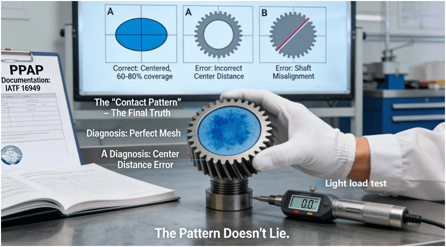
The “contact pattern test” is a simple, but very revealing, validation test. “A small amount of machinist’s blue (dye)is applied to the teeth of the worm wheel. The gear set is then rotated under light load through a number of revolutions. During this time, some of the dye will have been transferred to the teeth of the worm. This ‘contact pattern’ is a direct snapshot of the interaction of the theoreticaltooth geometries in the real world, under the very specific conditions of the assembled housing.”
2. Interpreting the Language of the Pattern
The location, size, and shape of the pattern are key indicators. An ideal pattern is one where it is centered over the tooth flank, covering 60-80% of the active area, signifying correct center distance, shaft alignment (90 degrees), and correct tooth geometry. A pattern centered at the tooth tip/root signifies a center distance error. A diagonal pattern signifies shaft alignment error(not 90 degrees) and lead error. These are major errors related to gear assembly and are responsible for concentrated stress, overheating, and excessive noise.
3. Institutionalizing Quality Assurance
This process is not optional for volume production. In a quality management system based on IATF 16949, the contact pattern reportis a requirement of the Production Part Approval Process (PPAP) documentation. This is evidence of a systematic approachto ensuring consistency in worm gearbox manufacturing and that the process is able to produce gearboxes that mesh correctly.
From 5 Prototypes to 500 Gearboxes: How to Ensure Your Pilot Run Doesn’t Become a Field Trial?
This last section discusses the process of moving from the prototype validation phase to the pilot production phase, and the key takeaway is to recognize that this is not just about the geometry of the parts.
1. The “Process Package” Handoff: The purpose of the prototype phase is to obtain a “validated process parameters”result, and this means not just the optimized cutting parameters for the gear, but also the heat treatment process, the shim pack used in the bearing, etc. A professional manufacturer will develop this “process package” and lock it into their control planfor the pilot production run, such that the 500th part is made exactly like the 5th prototype.
2. Qualifying and Freezing the Supply Chain: A prototype constructed with “boutique” or “sample” parts does not accurately represent the production process. The pilot process must utilize parts procured from the production volume supply chain. Accordingly, the prototype process should be used to qualify secondary supply chains for bearings, seals, lubricants, and even fasteners. This AVL can then be directly provided to the procurement group for the pilot process, removing a major source of variation and risk.
3. Replicating Validation with Production Intent: Finally, the test process used to validate the prototype must be replicable. The functional test process, performance validation criteria (efficiency, temperature rise, noise level), inspection process, etc., must be designed with production intentfrom the outset to be replicable to audit checks for the pilot production process. The continuity of validation, as espoused in product lifecycle management best practices, is what makes a successful prototype a successful product — a reliable product that can provide custom gear solutions.
Conclusion
In the context of high-demand power transmission applications, the art of superior worm drive engineering has progressed from the basic procurement of partsto a sophisticated discipline that encompasses mechanical design, material science, precise manufacturing, and product validation. By embracing the “Systematized Engineering Design”philosophy and working with a manufacturing company that has the requisite vertical integration competencies and associated data transparency, the high-torque right-angle drive can be converted from a potential failure mode to a key enabler of reliable operation.
FAQs
Q: What is a realistic lead time for a custom worm gear pair from design to prototype?
A: For a completely newdesign requiring full engineering analysis, machining, heat treat, and test, a 6-8 weeklead time is typical for functional prototypes. This also allows time for any possible design changes based on initial results from the DFM process. Subsequent production orders have much shorter lead times.
Q: How do you make sure the self-locking action is absolutely reliable, especially in the presence of vibration?
A: Reliability is engineeredinto the gear pair. The lead angle is designed 1°-2° below the dynamic friction angle of the specific material combination. This is then verified on a test rig where reverse torqueand shock/vibration are applied. The surface finish is also carefully controlled to provide a reliable and predictable coefficient of friction.
Q: What is the highest precision grade available for your worm gears (e.g., DIN standard)?
A: Through grindingand hard skiving techniques, we have consistently achieved DIN 5-6 gradesfor high-performance applications. For even higher reliability and mission-critical applications like aerospace and defense, we are able to achieve DIN 3-4 grades. The choice of grade is dependent on your performance vs. cost requirements.
Q: Will you supply a complete gearbox assembly, not just gears?
A: Yes, we will supplya complete gearbox assembly. This will include designing and manufacturing the gearbox casing, selecting bearings and integrating them into the design, and finally assembling and testing the gearbox before shipping it out to you. This is part of our complete worm gearoffering.
Q: How do we begin a project and obtain a meaningful quote without detailed drawings?A: We begin withthe essential performance parameters: Input Speed, Output Torque, Ratio, Duty Cycle, and Environmental Conditions. With this information, we can carry out a feasibility studyand develop a preliminary technical and cost proposal. The detailed quoting process will be completed after the conceptual design stage.